John Gerding
Member
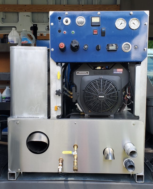
Hey guys how's it going... This is my official first Mikeys Board Post... I am looking for someone that has built truckmounts or at least knows a lot about the inner workings of a Last Step Injection system, Specifically how to plumb it correctly... I have been researching all I can about it and well there just is not much information out there to be had, or what is online is pretty vague... Anyhow so here is the situation, I have a Steamway Powermatic 2100 which I have rebuilt from the frame up with many modifications and alterations, The Powermatic originally came with a venturi style injection which did not work when I got the machine so I ripped it out. The only remnants left from the chem injection is the Chemical Tank located on the left side of the machine.
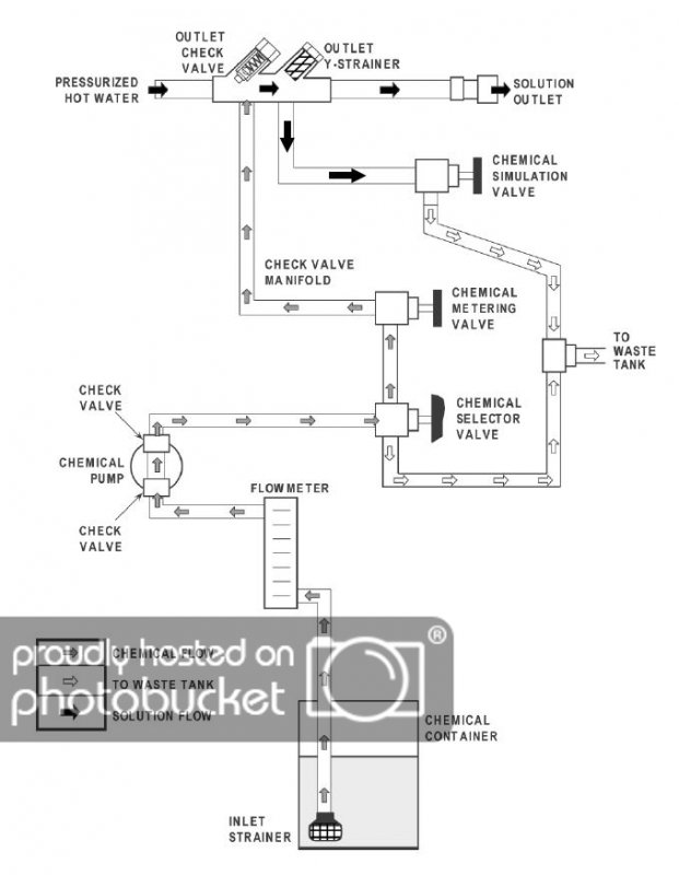
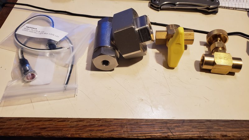
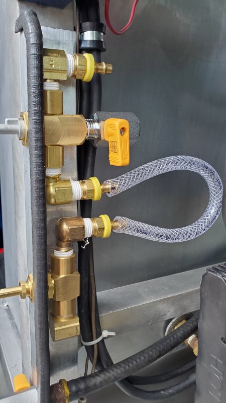
What little I have been able to figure out is the parts I needed, mostly the Chemical Pump, the Chemical Pump Adapter for my catpump, A needle valve for controlling the flow, a Y strainer for the solution outlet, a Dweyer flow meter, a few ball valves, and check valves. On the right side of chemical tank you can see where I have mounted, a 3 way valve for prime or chem, and the needle valve for flow control. The Dweyer Meter is still in the mail but you can see where it goes on the control panel. I guess the biggest thing I am confused about is where do I need to put a ball valve to shut off the pulse pump so the diaphragm does not get blown when I clean tile? does it need to go between the Catpump and the pulse pump to completely cut off flow from hitting the pulse pump? or can I just put the ball valve in line before the pulse pump? , I have included a diagram I scraped up off the web and it shows like a T splitter on one side after the chemical selector valve that goes to the waste tank for priming and a Chemical Simulation valve? I dont know what that chemical simulation valve is for... Or if I even need it? And the other thing is should I plumb the Chemical injection before my regulator and burner or only after the burner so the chemical does not get fried in the burner? Attached is also a picture of the pulse pump, 3 way valve and the Chemical Simulation Valve IF I need it...


What little I have been able to figure out is the parts I needed, mostly the Chemical Pump, the Chemical Pump Adapter for my catpump, A needle valve for controlling the flow, a Y strainer for the solution outlet, a Dweyer flow meter, a few ball valves, and check valves. On the right side of chemical tank you can see where I have mounted, a 3 way valve for prime or chem, and the needle valve for flow control. The Dweyer Meter is still in the mail but you can see where it goes on the control panel. I guess the biggest thing I am confused about is where do I need to put a ball valve to shut off the pulse pump so the diaphragm does not get blown when I clean tile? does it need to go between the Catpump and the pulse pump to completely cut off flow from hitting the pulse pump? or can I just put the ball valve in line before the pulse pump? , I have included a diagram I scraped up off the web and it shows like a T splitter on one side after the chemical selector valve that goes to the waste tank for priming and a Chemical Simulation valve? I dont know what that chemical simulation valve is for... Or if I even need it? And the other thing is should I plumb the Chemical injection before my regulator and burner or only after the burner so the chemical does not get fried in the burner? Attached is also a picture of the pulse pump, 3 way valve and the Chemical Simulation Valve IF I need it...


